|
|
Please
feel free to contact me with any and all helpful advice, it'll all get printed
and may save someone hours of grief!
A quick money saver, if your air shock
pipe is tatty don't spend £30 on a kit, see your local compressed air
specialist 6m for £2.
Here's a quick lesson in 1955-60 trans
interchange:
Old Cars Weekly October 25,
2001 By: William C. “Bill”
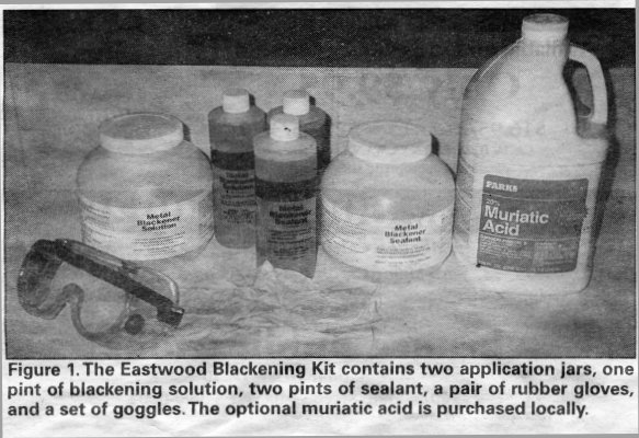
Anderson, P.E. Black oxide is a finish commonly applied to small fasteners and brackets
used in the assembly of automobiles. Its principal advantages are speed of
application and economy. Also, it is not dimensional, i.e., it is not a coating,
but rather a finish absorbed into the metal. However, it lacks long-term
durability and parts so finished ultimately rust over time when exposed to
repeated wetting and drying. There are specialty paints that approximate black oxide. However, they
alter the dimensions of the finished piece and are easily chipped during
assembly. For those wanting the real thing and not a paint copy, there are two
alternatives to produce a black oxide finish – purchase of a new piece
finished in black oxide or use the Eastwood Company’s Metal Blackening Kit
(see Figure 1). As mentioned in a previous column, I do not favor-refinishing fasteners,
particularly those whose strength is critical because the ravages of time
degrade the fasteners’ strength. However, for non-critical fasteners or in
those circumstances where the restorer wants to use a fastener with a specific
head design or other unique feature that cannot be purchased new, restoration on
an existing fastener is required. Applying a black oxide finish using Eastwood’s kit is simple. However,
this simplicity does not mean that care is not required to ensure a good result
– a uniform finish that completely covers the metal piece. The process is a
chemical and like any chemical process accurate mixing of ingredients, proper
operating temperatures, and rigorous attention to each step in the process is
key to success. The accompanying photos and the following text explain how to do
it. I am also including a few of my observations regarding the complete
instructions provided with the kit and related recommendations. At $49.95, the
kit is economical and will do many pieces before the chemicals need
replenishing. The blackening solution is a mild acid. Therefore, wearing rubber gloves
to protect your hands and safety goggles to protect your eyes is important. A
pair of rubber gloves and a set of goggles are supplied with the kit. Because
water rinsing is required, having a sink close by the area where pieces are
being treated is helpful. Before proceeding to finish parts, a few preparations are necessary;
Eastwood supplies on pint (16 ounces) of blackening solution. This must be
diluted in the application jar provided. The dilution specified is to add
distilled water (it is important to use distilled water to prevent contamination
of the solution) to within two inches of the top of the application jar. This
required 40 ounces of distilled water or a ratio of 1 part blackening solution
to 2.5 parts water for those wanting to make a larger or smaller batch. Second,
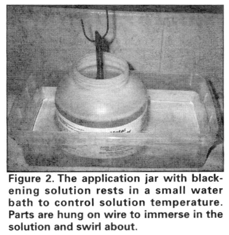
it is important that the solution be at least 75 degrees Fahrenheit. If your
shop is too cold, the solution temperature can be maintained by using a water
bath (a tub of water in which the application jar rests where the water
temperature is controlled); (see Figure 2). The Eastwood kit contains 32 ounces
of sealant and a separate application jar; no dilution if the sealant is
required. If the application jars supplied (they have a three-inch opening)
cannot hold the piece needing plating, any clean, appropriately sized plastic
container can be used. The application jars are also used to store the chemicals
between uses. Step 1 is cleaning the piece to be finished. There must be not rust, grease,
etc., on the piece. The finish cannot cover rust and grease and oils will act as
a barrier to the blackening solution. The best way to prepare each piece is to
first remove any oil or grease then use abrasive-blasting to remove rust and
finish up with a soaking in muriatic acid (a weak acid available in most
hardware or building supply stores) as a final cleaning. Abrasive blasting can
leave a surface that appears free of rust, yet retains rust particles not
visible to the naked eye. Even microscopic rust can prevent the blackening
solution from uniformly coating the piece. This is the reason for using the
muriatic acid. If a blast cabinet is not available for rust removal, then wire
brushing followed by soaking in a rust remover such as Oxy-Solv is necessary. Step 2 is immersion in the blackening solution (see Figure 2). On a piece of
metal that is truly rust-free, rusting will begin almost immediately. Therefore,
proceeding immediately from the acid cleaning to a thorough water rinse and onto
the blackening solution is necessary. The intermediate water-rinsing step is
necessary to prevent the acid from contaminating the blackening solution.
Eastwood recommends leaving the piece in the solution 20 to 60 seconds. Also,
moving the part around to ensure that all surfaces of the piece are treated, by
swirling the part on the end of the hanger (see Figure 2), is important. Bolts
and such can be rolled around in the application vessel with a plastic or wood
stick and then removed with a magnet. While Eastwood cautions against leaving
the part in the solution too long, it is also important that it be left in the
solution long enough. Therefore, I recommend erring on the side of a longer,
rather than a shorter, time in the blackening solution. Also, I recommend doing
only a couple of pieces at one time in step 2 to minimize flash rusting, letting
any extra pieces in processing wait in the muriatic acid. Step 3 is application of a sealant (see Figure 3). The piece being treated is
removed from the blackening solution, rinsed in clean tap water for 10 to 20
seconds, and then placed immediately in the sealant solution; no intermediate
drying is required. The piece should be left in the sealant for two to three
minutes, then removed and left to air dry. Drying may take from one hour to
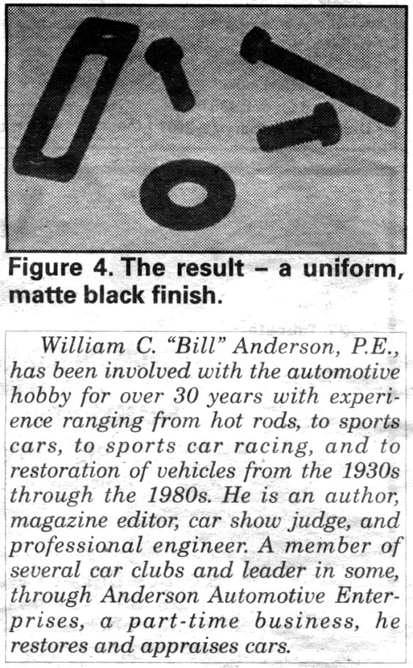
overnight depending upon conditions. If you have correctly performed all the steps, the result is a uniform
matte black finish (see Figure 4). However, if the part was not thoroughly
cleaned or flash rusting occurred between the cleaning and blackening steps,
rust color will appear once the blackened piece has dried. When the piece is wet
either after the cleaning or blackening rinse, the rust color will not be
obvious. If this occurs, re-clean the piece and start over. Properly performed, Eastwood’s Blackening Kit will economically provide
an attractive, protective black finish. The kit will do many pieces, and, each
chemical component can be purchased separately.
Keep spring in mind when planning winter storage Old Cars Weekly October 25, 2001 By: Wallace A. Wyss
Even though spring is months away, there are things that can be done
while preparing for winter storage so the car is ready the first warm spring
day. What do you do first? Here’s a compendium of information on how to store
your car for the winter. But keep in mind, different sources have differing
recommendations, and some tips contradict one another. Determine which works
best for you now or in the past.
First of all, some people argue that storing a car can be bad. Greases
liquefy, springs settle, and gaskets, bushings, and bearings can dry out. These
hobbyists believe collector cars should be driven on nice winter days to keep
everything lubricated.
When the roads are too bad, some suggest starting the car in the garage
if there is adequate ventilation. This will prevent lining the underside with
road salt, but won’t lubricate the rear end or the transmission like a nice
long drive will. If you do insist on intermittent storage with occasional
drives, top off the tank each time.
The tips that follow are for those committed to storing their car during
the entire winter: ·
Store
it dry: Water and moisture are the enemy, so avoid dirt floors because they
harbor moisture. Concrete floors also give off moisture, though it is not as
much. To keep the moisture from gathering on the underside of your car, line the
floor with a layer of insulation. That may mean a sheet of plastic or a 4ft. by
8 ft. sheet of plywood. ·
Raise
the car off the ground: You want
the tires off the ground so they don’t dry rot of get flat spots. The weight
of the car may also permanently damage the tires. Raising the car also allows
you to turn the rear wheels by hand every once in a while to keep the
transmission and rear end gears coated with oil. Placing the jack stands under
the axles and suspension rather than the frame keeps suspension components from
fully extending themselves, a type of stress the parts weren’t designed to
withstand. ·
Top
off your fuel tank: A car’s exterior isn’t the only place the water should
be kept away from. Water can also form inside the gas tank. Some experts believe
that filling the gas tank with fuel leaves less empty space in the tank for
condensation to form. Adding alcohol will also bind any water present. Other
sources recommend avoiding alcohol because it is corrosive to white metals and
can do damage to fuel gauge sensors, line couplings, and carburetors. Fuel
stabilizer in, run your engine to make sure it gets up to the carburetor float
bowl. Proponents of the empty gas tank recommend draining the tank and
disconnecting the carburetor gasoline line at the fuel pump to allow gas to
grain from the line. They then recommend disconnecting the line from the tank to
the fuel pump and blowing the line out with air. The, crank the engine over five
or six times to empty the pump and reconnect both gasoline lines. ·
Plug
it up: There are several recommendations for the spark plugs. Some believe
owners should remove the plugs and spray in light oil. Others buy a bottle of
carburetor treatment or transmission fluid and pour it down the carburetor until
the motor stalls. If you do this, expect to change the plugs before starting the
car up in the spring. Other sources recommend dumping oil down the carburetor to
lubricate everything, but again, expect to change the plugs in the spring. A
light machine oil like WD-40 will offer enough protection when sprayed down the
carburetor. ·
Crank
it up: Fill the crankcase up with a light preservative oil, completely
submerging the crank and all the piston rod bearings. Always park the car with
fresh oil. ·
Disconnect
the battery: Any auto parts store can supply a turn-off switch for your battery
so you won’t have to remove it. If you do remove it, store it outside of the
car and place on a trickle charger. Trickle chargers maintain the charge
whenever it goes below a certain amount. Make sure the battery is not set on
cement outside of the car. Place it on a block of wood to keep the current from
being drawn away. ·
Top
off the brake master cylinder: Brakes suffer from not being used for long
periods of time. Over time, brake fluid absorbs water and when the system is not
being used, the water gathers in the hydraulic fluid. It will cause pitting in
the master and wheel cylinders and ruin the rubber seals. Topping off the master
cylinder will give less room for condensation to form. Some people drain all the
fluid and put in D.O.T. 5 fluid, which will not absorb water. But only put in
D.O.T. 5 if you are prepared to bleed the whole system before taking the car
out. Also, be forewarned that D.O.T. 5 is slippery stuff and will find leaks
that the old brake fluid didn’t. ·
Set up
a picket line for vermin: Put mouse traps all over the storage place in a line
that’s easy to follow to check them all. Patrol your trap line periodically.
Imagine the smell if you catch a few and they rot in your storage place. You
wouldn’t be able to pay people to ride in your car! If you live in a wooded
area, beware of raccoons. They are clever beasts, and can find a way into your
garage if there is one. Check the building for any holes. Check under leaves
that may have gathered against the building or even roof air vents for possible
areas of access. Air vents can be covered with a screen. Check over the entire
building and see if there are any leaks animals could enter in, but especially
check for water leaks. I remember a friend's house that had a leaky roof. Water
pooled in the roof, then the pool became ice and a huge mess followed. Reject
any storage that shows leakage, best evident through stains or monitoring in a
rainstorm. Also, plug the car’s tailpipe, carburetor and air intake enough to
keep out mice in case they make it past the traps. ·
Seal
your car in a plastic box: This is another way to prevent vermin from getting
in. And not only will a plastic covering keep the dust off, it will prevent
moisture from entering. Companies like Car Jacket and PDK can supply these bags
at a reasonable cost. Contact Car Jacket at 800-522-7224 or PDK at 800-735-2822.
Most bags sold by these companies come with a desiccant to absorb moisture. ·
Prevent
moths: Owners of prewar cars with wool and cloth interiors should especially
beware of moths. One clever idea to prevent moth damage is to use diatomaceous
earth, a natural insecticide, sprinkled over the carpet and seats. It can simply
be vacuumed out in the spring. Radio stores sell this product. ·
Use a
care cover: If you are going to use a car cover, get one that breathes rather
than a plastic one. These should be used indoors where they can’t get wet. If
allowed to get wet, they will trap moisture against your car. A cover used
indoors will also help keep animals out and protect the paint from bird
droppings. ·
Drum
brakes: Back drum brake shoes off from the drums to keep them from rusting in
place. One they are backed away, the inside of the drum can be coated with a
thin layer of grease to prevent rust. ·
Convertibles:
Don’t store the car with the top down. If you do, it may retain stains of any
condensation that gets in between the layers of the top. Leaving the top up
prevents animals from entering the car’s interior and wrinkles from wrecking
the top. ·
Security:
Install good locks. I suggest the type of padlock where the lock case curves to
cover the part that goes through the hole as these are harder to cut open with a
bolt cutter. Paint or cover windows, if possible. If there is electricity,
install an outdoor motion light. ·
General
tips: Wash and wax the car prior to storage. Some believe it’s worthwhile to
apply a fresh coat of wax and let it set without buffing. Experts also recommend
applying car was to chrome parts. A few even suggest applying a film of oil to
parts, but this collects dirt and is hard to clean later. Your car’s best
friend is cleanliness and dryness. Last but not least, keep a list of what you
did so you can do it all in reverse when you take the car off the stands in
spring. With a fresh oil change again in spring, your car should be ready to go. For 54's, click to enlarge
Hotting up flathead sixes and straight
eights.
Since
several pontiac-1950er's have asked in the past about hot rodding the flathead
sixes and straight eights, here's what I've learned over the years...
GM makes a variety of
speedo gears for their transmissions.
Replacement speedo gears
are made of nylon, and come in a variety of colors and sizes. As you correctly
surmised, there is a direct correlation between speedo gear size and the rear
end ratio.. i.e. A "red" drive gear will correctly mesh with
four of the twelve possible driven gears, that cover the overall final drive
ratio spread of a "medium" rear end ratio application...Although I
don't have the speedo gear chart with me, here's my recollection as to what it
says: Drive Rear End
Gear Ratio
High series 2.56-2.89
Med series 3.07-3.23
Low series 3.42-3.73
Race series 3.90-4.30
You
can interchange between series, but not among...The best way to get the correct
matching "pair" of gears, e.g. the drive gear and the driven gear, is
to run the car on a chassis dynomometer. This takes into account all of the
variables, including tire diameter... Obviously, you should think about speedo
accuracy requirements before you reassemble the trans, since the drive
gear is pressed onto the mainshaft with the extension housing removed. In the
dyno situation, after the computer determines the correct "pair", the
car is placed on a hoist, the driveshaft and rear extension housing
removed, the "wrong" drive gear pressed off, and the "right"
one pressed on. The computer has already selected the right "driven"
gear, which slips into the speedo cable housing (bolted to the extension
housing)...You might try: http://www.bobsspeedometer.com
or http://www.paspeedo.com
Be
prepared to supply tire diameter and rear gear ratio when you talk with them...
Good
luck! Rick Gonser
POCI Senior Technical
Advisor pontiac-1950s@yahoogroups
Co-Facilitator
The bushings in the spring ends are no problem, the bushes found in a casting
riveted to the chassis are. They have a very thin outer wall making it nigh on
impossible to remove with a piece of threaded bar and a suitable socket. I found
it far easier to drill and grind out the rivets and remove the casting, then
replace the bushings in a vice. I found this out the hard way (about 6 hours and
an air-chisel!). look in links for suppliers of the bushings.
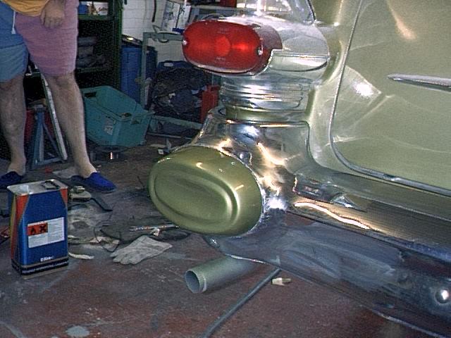
A common tin-worm area for our cars, these are available new, but at £200+ a
pair are out of my range at present. I ground out the rot, repaired the holes
with glassfibre and matting, then filled and sanded, finishing off with body
colour. I think they look ok, and what's more cheap too!
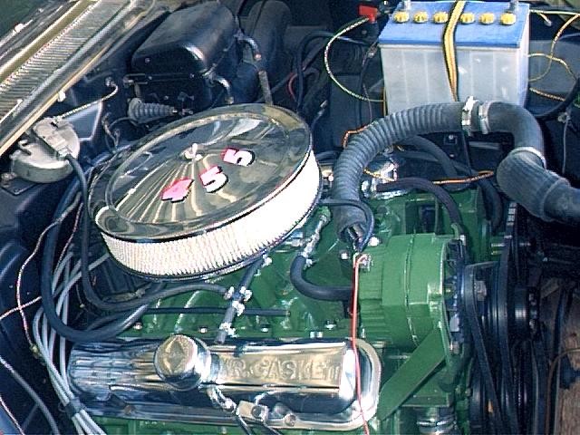
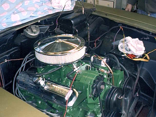
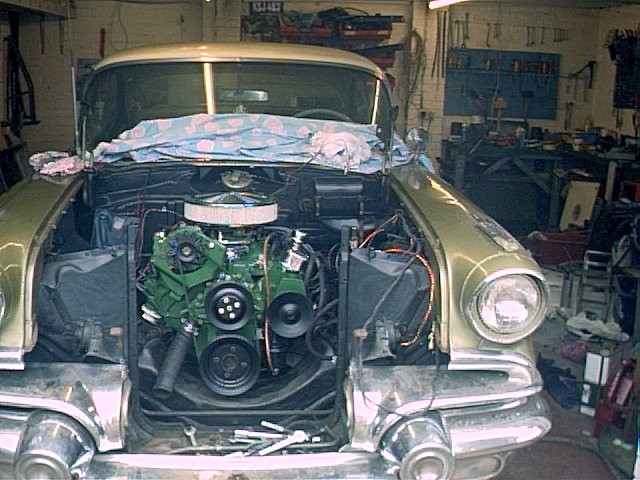
Providing you have the facilities to fabricate new engine and transmission
mounts this isn't as difficult as it seems. The main difficulty being space for
the exhausts be they cast or tubular. John Hugentober and I both bought cars
with this job having been done to a less than amazing standard. it is a tight
squeeze, cooling is luck of the draw, in my case I supplemented the
standard radiator with twin Peugeot fans on a homemade bracket, this proved
marginal so I removed the standard grille bringing the temp down by 5 to 10
degrees. See the pics below for more gen.
Rewiring the car.
Not as difficult as I first imagined, I bought all the components and tools for£200,
the job itself took me a week. Remove the old loom in one piece, then lay it out
on the floor having removed the tape. Then identify each wire and working from
these measurements build the new loom. One of the most worthy jobs you can do.
the Americans saved money on cars in this era by using wire of JUST enough
current carrying capacity. I up-sized all my wires to give a good safety margin.
Just think no more breakdowns!!!!! marvelous. one book I can't praise enough is
Tex Smith's How to do electrical systems by Skip Readio, it seemed out of date
when I bought it but was a mine of information. While I'm in the mood for plugs,
Vehicle Wiring Products in Derbyshire (0115 9305454) were used for the wire etc
and were very helpful with the multitude of questions I fired at them.....thanks
again lads !
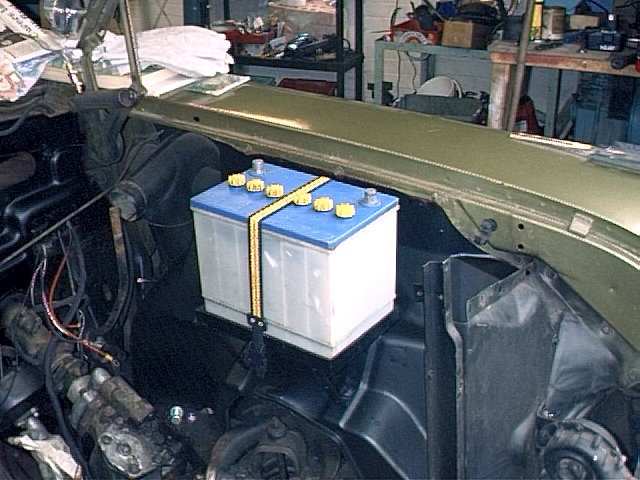
I'm not sure where i picked up this priceless piece of info, but if its yours
please get in touch for credit! You've helped so many people! BUY A
105 AMP "CS" ALTERNATOR!!!!
PLEASE NOTE; Always
disconnect the battery when doing electrical work on your car! What I'm going to try
to cover is the conversion from an external regulator alternator to a more new
"SI" internal regulator alternator. In the latter part of the page,
I'll cover changing over to a new "CS" alternator. I first did the "SI"
conversion on my 64 Chevelle using an old alternator that I had around the
garage. The bracket configuration is similar to what is in a 69 Camaro (long
water pump and the alternator mounted on the shotgun side of the engine). After the car was on
the road for a while, the alternator started acting strange and the voltage
output wasn't constant. That gave me a perfect reason to do the conversion to
the new style "CS" alternator! There wasn't any problem with the
wiring changes, it was just that the "SI" had seen it's years. I have to add a word
of caution here, the colors of the wires called out are the "standard"
colors and I can't swear that your car's wiring loom matches. Please blame GM
and not me!
When you convert from
the external regulator alternator, you no longer need the regulator that is
mounted on the radiator support. You also don't need some of the wiring that is
present in the loom. The diagram below
shows the original connection at the old regulator. (I'm sorry, but the wire
that is colored yellow, is really white)
The next diagram shows how you modify the loom at this location.
Notice that the blue
wire is jumpered to the brown wire. The white wire and the orange wire are just
capped off so that they will not short out to anything. This next diagram
shows what you have to do at the new alternator.
The wire that goes
from the "BATT" terminal to the #2 terminal is a new wire that you
will have to add. You can use a 14 gauge wire. The white wire (shown
yellow) just gets capped off. You will need a new
connector to fit the new alternator and they can be purchased at almost any auto
parts shop. Due to my being
bothered by the "extra" wire being in the loom, I totally removed the
dead white and orange wires. I also wired the brown wire to the alternator
directly. It just gets rid of some extra length of wire.
The prior
paragraph has caused me a lot of e-mail feed back and hopefully the following
information will clear it up. In my final wiring configuration, the "brown
wire" comes from the alternator indicator light, through the firewall
connector, and directly to the alternator. The result is electrically the same
as the diagram at the top of the sheet, just cleaner. The diagram above would
have the brown wire coming out of the connector at the firewall, going toward
where the regulator was, connecting to the blue wire, then the blue wire goes to
the alternator. As I said, I cleaned up the wiring (and in the process, dirtied
up the wording). In order to ensure
good connections, I recommend that you always solder the connections and then
use heat shrink tubing to seal it.
"CS"
alternators; I just got done
converting to a 105 amp "CS" alternator. It's fantastic and the
conversion was a piece of cake. Here is the low-down; I got mine from a
local rebuilder that was recommended by my local auto parts store. I need to
find out what car type, the configuration I got, was out of. I paid a little
more than $110 for it and that included the $40 core charge and electrical
connector. An "SI" alternator is only good for a $10 core charge and
most rebuilders don't even want them. He didn't charge me to swap the pulley to
a "v-belt" type. It has a typical "rebuilder" silver paint
job that will have to be changed at a latter date. There are two
different physical sizes of "CS" alternators and I recommend that you
stick with the smaller of the two. In stock configuration, you can get 105 amps
and I feel that this should be more than enough unless you are running a
"boom box" stereo playing rap music for the world (I don't like these
people!). The first thing that
you have to look for is one that has the "straight flanges". What I'm
talking about here is the mounting flanges. One of the flanges is for the pivot
bolt. The other flange should be directly across from it and is for the bolt
that goes in the slotted bracket. (I'm going to refer to this bolt as the
tensioning bolt) I asked the rebuilder
what type (and year) car the alternator that I used came out of and here is the
story. You want the alternator from a 89 through 93 full size GM truck. This
includes the Bubs and Tahoe's. That's not to say that it wasn't used on other
vehicles, I just didn't want to drive him crazy cross-referencing. The flange for the
tensioning bolt is tapped for a metric bolt. The bolt is 8mm and the thread
pitch is 1.25 mm. You have to make sure that you get the correct pitch due to
8mm with 1.00mm pitch also being real common. Now you have to get one of those
dang metric 13mm wrenches. You really don't have
to worry about the "orientation" of the connector (in the body) due to
the fact that it's possible to unbolt the housing and rotate the rear cover. As far as I know, all
of the "CS" alternators come with a pulley for serpentine belts. When
I got mine, I had the rebuilder just swap a "v-belt" pulley on it.
It's the same pulley and fan as what is on a "SI". Most of the connectors
for the "CS" alternators are four wire. Don't worry!! You will only
use two of them and the wiring is the same as the "SI" above! On the connector that
I got, there were four wires and the body of the connector had identification
letters. Here are the id letters and the color wires (don't count on the colors
to be the same as what you get). "S", this
was a heavy gauge, red wire. "F", this
was a small gauge, brown wire. "L", this
was a small gauge, brown/red wire. "P", this
was a small gauge, brown/white wire. The red wire from
"S" gets connected back to the output terminal of the alternator just
like in the "SI" swap. The brown/red wire
from "L" gets connected to what is shown in the diagram above as the
blue wire. It's this wire that comes (indirectly) from the idiot light and it
energizes the alternator. The wires from
"F" and "P" are not used! Mounting the
alternator was just a remove and replace thing. The only bummer for my
installation is that the spacer that goes between the block and the alternator
should have an additional support bolt into the alternator (if using the "SI")
and there isn't correct placement of the bolt hole in the "CS"
alternator. As an additional note;
AC Delco sells a "conversion" wiring loom if you are changing from a
"SI" to a "CS" and it is nothing but a few short wires and
two connectors. One connector plugs into the existing wiring loom connector that
was plugged into the "SI". The other new connector plugs into the
"CS". What's real important to note is that there are two different
types. One is "non-resistor" and the other has a resistance in it. You
want the "non-resistor" one if you are going to keep the idiot light.
Use the "resistor" one if you are getting rid of the idiot light. Be
sure to read the "notes" section of this page before jumping!!
NOTES; Why go through the
trouble? Well, the "SI" alternators are easier to get and have a
higher out-put. The "CS" alternators are even
better! What about those
"single wire" alternators? From what I have heard from some very
knowledgeable people, they tend to over heat and are not as durable. I also
would question if the alternator light would function. Hey, it may be called an
"idiot" light, but I'd rather it warn me about a problem then sit at
the side of the road crying. While in an automotive
electrical rebuild shop buying my new CS, the man said that the one wires really
didn't have any overheating problems. So, I really don't know who to believe. He
also said that it's possible to make up a "single wire" CS alternator. And what about the
idiot light? Well, the electricity that goes to energize the alternator (through
the brown wire) comes from the idiot light. This leads to an interesting tid-bit,
the alternator needs to see some resistance in this line. That resistance is the
bulb! If you try to be "custom" and use a LED, there isn't the correct
resistance and the alternator will not work correctly! You can't just by-pass
the light! Why can't I turn off
my engine? You wired up the alternator wrong! Hey, it's only two small wires but
you can swap them. What happens is that the output of the alternator feeds it's
self and even though you turned off the ignition, as long as the alternator is
spinning, it feeds the car and keeps running. Ignition
Tuning
On
a mechanically sound car, optimize the ignition timing before playing with the
carb. Even if the jets are off, you'll never find the solution until the
timing's right. Typical
stock-type distributor curves have too much centrifugal advance built into the
distributor. Assuming the use of 92-octane unleaded premium pump gas, less than
9:1-compression small block Chevys like about 10 to 11 degrees total advance in
the distributor (20 to 22 as read on the crank), with 16 degrees initial timing
at the balancer (for 38 degrees max crankshaft advance). The
centrifugal advance curve should start around 1,200 rpm and be all in by 3,500
rpm. A lightweight car with a big solid-lifter cam (more rpm capability) and
deep rear gears will tolerate more overall advance that comes in quicker (as
early as 2,800 rpm). High compression ratios call for backing down the timing to
avoid street-gas-induced detonation. Advancing
the timing until the car "pings", then backing it off, doesn't always
produce the best horsepower. Try advancing and retarding the timing in 2-degree
increments to see if the car speeds up or slows down. Vacuum
advance is good for street cars, as it promotes improved part-throttle fuel
economy and driveability. Because the vacuum advance doesn't function under
wide-open-throttle, you don't lose anything by leaving it hooked up. Hard-Running
street cars may benefit from going to a spark plug that's one step colder than
stock (but check for evidence of fouling). With high-output electronic
ignitions, gaps of around .040 inch are usually a good compromise between
getting a strong spark and preserving coil longevity.
Carb
Tuning
First
of all, make sure that you've got the ignition timing set correctly before
you start trying to adjust the carb. Before
you make any major carb modification, make sure that the basic adjustments are
correct. Set the idle mixture screws to give you the highest vacuum reading or
the highest idle rpm using either a vacuum gauge or a tachometer. Although
it won't affect WOT (Wide Open Throttle) horsepower, a proper accelerator pump
shot is important to avoid an off-the-line bog, especially with Holley double
pumpers. Fortunately, on a Holley you can play with the pump-cam position,
shooter size, and pump cams to achieve optimum response. Non-Holleys may have
limited accelerator-pump tuning ability, but at a minimum, they always have a
rod you can bend. If your car does have an off-the-line bog, a basic
rule-of-thumb is: If the car bogs, and the exhaust is black, the mixture is too
rich. If the car bogs and the exhaust is "normal" the mixture is too
lean. Jets
have a definite affect on WOT power numbers. On a performance application
running steep rearend gears where fuel economy is not a factor, jet the
primaries and secondaries up or down in equal increments, unless the spark plugs
offer a visual indication of uneven fuel distribution. Some carbs use metering
rods instead of jets, but the principle is the same.
Wheel
Alignment is the mechanics of keeping the steering in proper adjustment. Correct
wheel alignment is essential for easy and efficient steering and to avoid
abnormal tyre wear. All it takes to throw a front end out of alignment is one
bad pothole or one good bang against a curb. Even without abuse, front wheel
alignment will change under normal, everyday driving conditions. The change may
be so gradual that it is not noticed at first. The first sign of something wrong
usually shows up on the front tyres, which develop peculiar wear patterns that
will severely shorten the life of the tyre. When these appear, the vehicle
should have its alignment checked.
Having just replaced the front end bushings and dampers on the starchief
I had a full 3 angle track carried out and must say it’s the best £50 I’ve
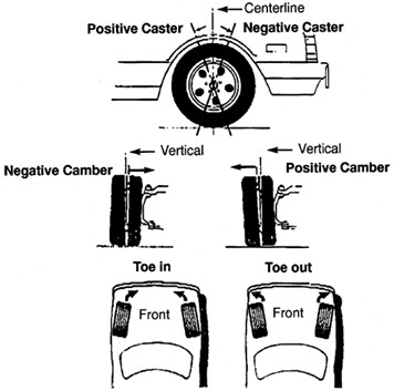
spent on the car, it feels like a different car to drive. Front wheel alignment is determined by the
interrelation of three basic steering angles:
Camber
Inward
or outwards tilt at the top of the wheel. Too
much tilt inward known as negative camber causes premature wear on the inside of
the tyre. Caster Will
not affect tyre wear, but will affect the steering ability and ride of your
vehicle. Backward
tilt, know as positive caster, will keep your wheels pointing straight ahead and
when turned will raise the vehicle on one side in either direction, thus the
wheel returns due to the weight of the vehicle after a turn. Too
much tilt will cause the vehicle to bump shimmy (shaking of steering wheel when
hitting bumps) and also give a rough ride. Forward
tilt know as negative caster is not something you want on a vehicle as the
steering will not return and will wander erratically. Too
much difference in the caster readings from offside to nearside can cause the
steering to pull one way. Tracking Known
as toe in or toe out ( tyres running parallel to each other). Too
much toe in or toe out especially, will wear the front tyres very fast. Too
much toe in will show up as a knife edge on the tyre tread to the inside. Too
much toe out will show up as a knife edge to the outside of the tread. Correct
toe in is critical. The warning signs suggesting the need for alignment are easy to spot. They include:
Radiator
Caps are Important Too Old
Cars Weekly, May 31, 2001 By: Bill Siuru In
an “open” system found in older vehicles, excess pressure escapes into the
atmosphere through an overflow tube. As the system cools, air enters through
the overflow tube and coolant is lost. Therefore, “closed” or reservoir
cooling systems are used in later model vehicles. Here, as the coolant
expands, it goes through the overflow tube into a reservoir. The radiator cap
now serves as a vacuum relief and siphon valve allowing coolant to be siphoned
back into the radiator as the engine cools and coolant contracts. Radiator
caps also serve as a pressure relief valve to prevent excessive pressure in
the cooling system after the engine is turned off. Unchecked, high pressure
could cause damage to the radiator, heater core, hoses or water pump seal. The
pressure cap also prevents radiator hoses and tanks from collapsing due to the
partial vacuum that would be created if air was unable to enter. Check
the radiator cap during routine maintenance, when coolant is tested or when
coolant is replaced. Check only when the engine is cool. With the engine off,
place a rag over the cap and remove it. Turn it counter clockwise about a
quarter-turn until it reaches the safety stop. Allow all pressure to vent
before removing the cap by pressing down and turning it counter-clockwise. On
some vehicles, the radiator cap is located on the overflow reservoir. With
the cap removed, pressure test it noting the maximum pressure when the cap
valve opens. Caps come in a variety of pressure ranges: 4-pound caps
(3-5lbs.), 7-pound caps (6-8lbs.), 13-/14 pound caps (12-16 lbs.) and 15-/16
pound caps (12-16 lbs.). The cap should be replaced if it fails to hold the
rated pressure for one minute. Using a cap with the wrong pressure rating can
cause over-pressurization or too low a coolant boiling point if the pressure
rating is too low. Since
radiator caps are so important and are relatively inexpensive, just replace
with a new one. Also inspect the overflow tube connecting the filler neck to
the overflow reservoir for looseness, cracking or obstructions. Check the
radiator filler neck sealing surfaces for nicks, dents or corrosion that could
impair sealing. Inspect gaskets for looseness, cracking, hardening or other
damage that allows pressure leakage and coolant to escape.
“Check those radiator and
heater hoses”
Old Cars WeeklyJune
7, 2001 By:
Bill Siuru I
recently had a heater hose burst on my seldom-driven, 25-year-old car. The hoses
all looked great from the outside, but one failed even though I had driven only
a few miles and the engine had barely reached operating temperature. The problem
was electrochemical degradation (ECD), which causes the cooling system to act
like a battery. The
active metal in the aluminum alloy thermostat housing and radiator are the
negative electrodes or anodes. The coolant, with its ionic corrosion inhibitors,
is the electrolyte. The hoses containing coolant and oxygen serve as the
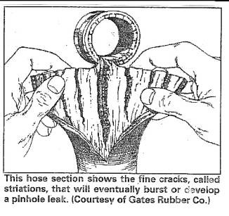
positive electrodes or cathodes. This
battery-like reaction produces and electrical charge that leads to the
striations within the tube wall. These fine cracks extend from inside to the
outside near one or both ends of the hose. The coolant seeps through these
cracks, attacking the hose reinforcement as it wicks along the length of the
hose. The cracks, accelerated by high tempe5ratures, flexing and vibration, grow
larger and deeper. Eventually, the hose springs a leak or ruptures under normal
pressure.
Engineers
at the Gates Rubber Company, who first discovered and diagnosed the problem in
the mid-1980’s, estimate that 95 percent of coolant hose failures are now
caused by ECD. Failures most often occur in upper radiator, bypass and heater
hoses – the ones most likely to contain air when the vehicle is not running.
Like rust and metal corrosion, ECD continues to destroy hoses even when the
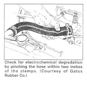
engine is off and the vehicle is in storage. A
hose may look almost new, but since it goes bad from the inside out, appearance,
alone, is not an indicator of when a hose is about to fail. However, you can
feel the effects of ECD by squeezing the hose near the clamps. Failure normally
occurs within two inches of the hose ends, not in the middle. Perform
the test when the engine is cool. Use fingers and thumb, not the whole hand, to
check for weakness. Check for any difference in feel between the middle and the
ends of the hose. If the ends feel mushy, the hose should be replaced
immediately. Make sure to inspect heater and other small hoses since the smaller
the dimensions of the hose, the faster ECD damage can occur.
Gates
research shows that hose degradation occurs in vehicles with as few as 25,000
miles on the coolant hoses. Stop-and-go driving or extended idling can
accelerate the problem. The solution is to replace hoses, even ones that look
good, more frequently. Never let them go longer than four years. You
can remove hoses and inspect them internally, but why not replace them since by
removing hoses you have already done the hardest part of the task. Electrochemically
resistant (ECR) hoses are now available. For instance, Gates offers hoses made
of a EPDM formulation that resists the destructive effects of ECD. The ECR hoses
have gone 200,000 miles or more with no damage. Additionally, the Gates ECR hose
inhibits coolant from permeating through the hose walls, which results in water
loss and an imbalance of the antifreeze. (Too much antifreeze can be as
detrimental as too little antifreeze concerning the boiling and freezing
points.) Finally, replace clamps when replacing hoses. Although
today’s clamps are usually made of stainless steel to resist corrosion and
damage, they still use carbon steel screws, which can fatigue and lose strength.
Old
Cars Weekly June
7, 2001 By:
William C. Anderson, P.E. Underpinning every car restoration are hundreds of bolds, nuts, washers,
and screws – fasteners all. Without them a car would be just a pile of metal,
wood, cloth, and plastic. Some fasteners are critical in that they hold together those pieces that
make the car go, turn, and stop. Others are not critical in that sense, yet they
are no less important to a successful restoration. It is not enough that
fasteners be of the right size, they must be of the proper strength. The
cardinal rule is replacing or reusing fasteners is this: Always replace a
fastener with one equal to that being replaced and do not reuse a fastener if it
does not satisfy the specifications for the original. Many enthusiasts spend hours cleaning and restoring the original
fasteners. From my perspective, this is a waste of time. More important,
however, is that these “restored” fasteners may no longer have the strength
to function properly. Dependable fasteners are a must. Therefore, this article
provides some basic information regarding the manufacture and use of fasteners. Materials
Fasteners are made of steel. There are a thousand different compositions,
each intended for a specific purpose. These many compositions can be classified
as five basic types: carbon, alloy, stainless, tool, and special-purpose steel.
Aluminum and titanium alloys and plastics are also used to manufacture
fasteners. However, this article concentrates on the most common material, steel
and its alloys. Steel and steel alloys used in fasteners may be heat-treated.
Heat-treating is a process that subjects the fastener to heating and cooling in
a way that yields specific properties. While any metal can be heat-treated its
use for fasteners is to improve strength or hardness. Strength
Bolts, and their corresponding washers and nuts, are graded according to
strength as well as thread pitch and type. The higher the load and/or the
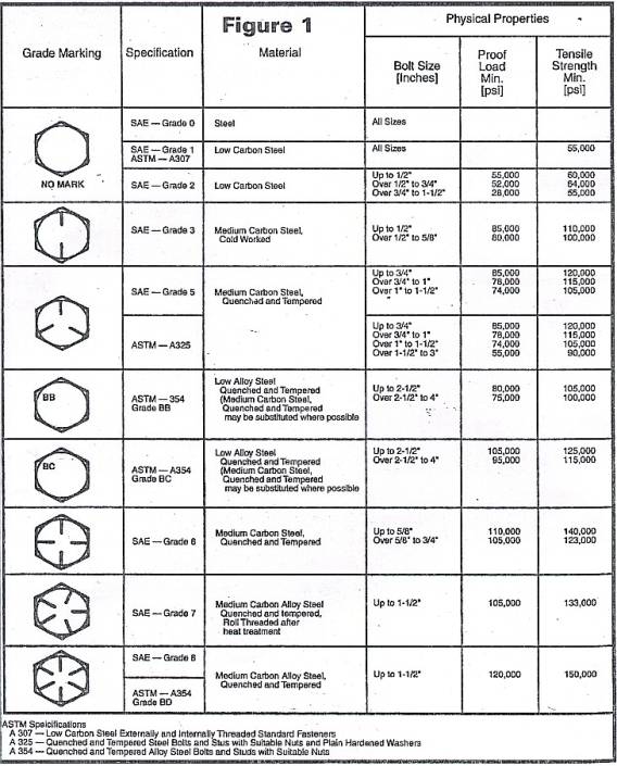
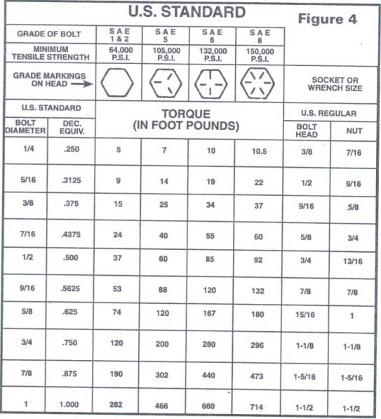
greater reliability required, the higher the grade of fastener. The Society of Automotive engineers (SAE) grades automotive fasteners
from 1 through 8. The grade is indicated by markings on the fastener head.
Figure 1 provides illustrations of these markings and the corresponding SAE or
ASTM (American Society of Testing Materials) specification, material, and
physical properties for each. If nuts are used, it is important that their
strength be equal to or greater than the strength of the bolt with which they
are used (see Figure 2). The same is also true for washers. Remember, the
ratings in Figure 1 are for new, properly manufactured fasteners.
As
indicated in Figure 1, the grades differ in their tensile strength. Tensile
strength is defined as the amount of load required to break or fracture a
material by pulling it longitudinally and is expressed in pounds per square inch
(psi). Note that Grade 8 fasteners have about twice the tensile strength of
Grades 1 and 2. Another criterion is shear strength. Shear strength is a measure
of the load applied at 90 degrees from the axis of the bolt required to break or
fracture the material. It is about 60 percent of the tensile strength.
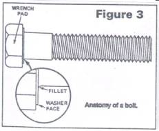
Failure Fasteners Can fail for many reasons. One reason is that the bolt is not strong enough for the intended application. Another is that the fillet at the bolt head (see Figure 3) may become scratched, weakening the bolt and causing the head to break off under tension. The purpose of the fillet is to reduce the stress concentrated where the shank meets the head.
To
protect the fillet, always correctly install a smooth washer.
Installing a washer may seem a simple task, but many get it wrong. The correct
way is to install the smooth side of the washer towards
the bolt head. Every flat washer has a rounded side and a sharp side that
is usually visible and can always be detected by touch. These causes of failure
can defeat even a new fastener that is structurally sound and satisfies its
manufactured dimensions. This is generally not the case with original fasteners
that have deteriorated due to exposure to the elements. Still, another mode of failure is fatigue. This can be caused by over
tightening or cyclic stressing from repeated loosening and tightening or from
the loads applied. For all these reasons it is far better to use new fasteners
than the original(s). It also saves time cleaning, bead blasting and plating,
which can also alter the original fastener’s characteristics.Sources Many fasteners needed for automotive restoration can be readily purchased
at local automotive supply stores with a little careful shopping. As a general
rule, use a Grade 5 fastener on any
component related to control. An excellent source of automotive fasteners is Au-ve-co®
products. This company not only has all the necessary grades, it often has the
correct finishes (zinc, cadmium, black oxide, etc.) and it is a source for
hundreds of unique fasteners used in body and trim applications. The one feature
this company cannot supply is the company trade mark of the original fastener
manufacturer. Where having the correct head markings are important for show
competition, reproduction manufacturers have often filled this need. Au-ve-co and other manufacturers of automotive and industrial fasteners
do not sell retail, they sell to the trade through sales representatives.
Consult the Yellow Pages in your area under “Fasteners” to locate a
representative near you. Some will sell to individuals or identify one of their
outlets that will. However, you must buy in quantity; typical packages range
from boxes of 25 to 100 items. Even by buying boxes, you will save money plus
have some left over for your next project. It is also important to deal with reputable suppliers. While the
“Fastener Quality Act” of 1990 (Public Law 101-592) makes it a crime to sell
counterfeit bolts (miss-marked as to grade), counterfeiting continues. Application
Having the right size and grade of fastener is just part of what is
needed for success. The other part is properly tightening the fastener. Every
fastener has a correct torque – under-tightening can cause parts to work loose
while over-tightening can exceed the fastener’s yield strength and contribute
to failure. Yield strength is the load at which the bolt begins to stretch
without increasing the clamping load. Depending upon material, it may be about
90 percent of the tensile strength. When a fastener is tightened, it endures stresses of tension and twist.
Tension is desired, but twist also occurs because of friction, yet only the
tension remains after the bolt is tightened. About 50 percent of this friction
occurs at the bolt head and nut faces with 40 percent spread along the bolt
threads. Figure 4 provides the recommended torque amounts for fasteners of varying
size and type. These values are for clean, dry threads. Lubricant or plating on
the fastener faces and threads will alter these values. Use 15 to 25 percent
less torque if the fastener is lubed with graphite, Teflon, etc. Zinc plated
fasteners require 15 percent less torque and chrome and cadmium plated fasteners
require 25 percent less. The values given in Figure 4 are a last resort. The
best source is the shop manual for your car; pay close attention to any
conditions, i.e., oiled or dry, associated with the torque values supplied by
the car manufacturer.
Keeping them tight
Keeping fasteners tight is as important as the initial tightening. There
are many locking devices. Another cardinal rule is that locking devices should
not be reused. Helical spring lock washers, the most common, work by maintaining
a constant load against the head of the fastener; they should be used on the nut
side, not the bolt. Spring steel lock washers with internal or external teeth
work by biting into bolt head or nut surfaces. External-teeth lock washers are
good for improving electrical contact between a fastener and cable terminal.
Castellated nuts used with cotter pins or safety wire are the preferred locking
approach for any part that rotates or moves, such as the hub nut on an axle
shaft. Lock nuts are of two types. The deformable type uses mechanical
distortion to bind on the bolt threads. These cannot be reused and often damage
the bolt threads. Lock nuts that have a ring of plastic or nylon also create a
bind on the threads. These fastener type cannot be used in high temperature
applications of 250 degrees or more; some can be reused and others cannot.
Finally, there are thread-locking compounds that keep the fastener tight by
filling the gaps between the threads of the bolt and nut. There are several
types of these compounds; removable, permanent, high temperature, etc. These
compounds are especially resistant to vibration. Summary
Properly using fasteners is key to a successful restoration. While
fasteners are deceptively simple, they are one more part of the automobile that
has been engineered for a specific purpose and condition of use.
Replace
the resistance wire that ran to your points system, from the fuse block, with a
12guage wire (pink insulated if you want to remain factory compliant) and hook
it up to the HEI "BAT" terminal. Okay, so you want more; The points
system has two wires running to the coil, one is the above mentioned resistance
wire. This wire provides reduced voltage to the coil while the engine is
running. The other wire originates from the starter R terminal (the #6 stud
furthest from the engine block on the starter solenoid). This wire provides full
battery voltage to the coil during cranking only. You
finally have the lug in your hands with a bit of resistance wire still attached,
carefully pry open the crimp to remove the old wire. Feed your new 12 gauge wire
through the fuse block (remember, the lug has to be inserted from the
"inside"), strip off an appropriate amount of insulation, gently crimp
it onto the lug, and then solder it for a secure and electrically tight
connection. Reinstall the lug into its slot, steal a wipe of the grease from the
fuse block and coat your new lug. Reinstall the fuse block. Tip
#1:
If your short term memory is like mine, mark, make a diagram, whatever it takes,
to indicate which of the empty slots in the fuse block corresponds to the lug
feeding the ignition system. Tip#2:
If you are experiencing part throttle pinging with the HEI, you probably have a
20 degree vacuum advance can. Most HEIs have a ridiculous amount of advance
here, which is a detriment when you start experimenting for optimum timing. Pull
the distributor cap and you will find a number stamped on the top of the support
bracket near the can. This is the cans advance, it can be anything from 8 to 24
degrees. A 10 degree vacuum can is ideal. It is available from AC Delco Parts,
or your dealership. Canadian AC Delco part number: D1370A Tip#3:
If you are experiencing a pinging under slight loads or going uphill (part
throttle) , hook your vacuum advance to manifold vacuum, this will cut down on
the amount of vacuum advance and hopefully rid you of the pinging. Excessive
pinging will require a deeper look into your ignition timing and/or mechanical
advance rates. Thought
#1:
Ported Vacuum or Manifold Vacuum? Manifold vs. Ported, its a never ending
debate. Depending on the age of who you ask, and their own experiences you still
have a 50-50 chance of one or the other. Ported vacuum is the choice of the
factory. It is also my recommendation to start with ported vacuum. Depending on
what level of modifications you have done to your engine, your driving style,
and your vehicles characteristics its a point of debate. Each presents its own
set of advantages and disadvantages. My suggestion is to just try both and
observe how your engine behaves for your driving style. This
information is only intended as an overview and may not include all the
necessary information, data, or facts to complete the swap.
Troubleshooting a low or spongy brake pedal and
related problems
Old Cars Weekly
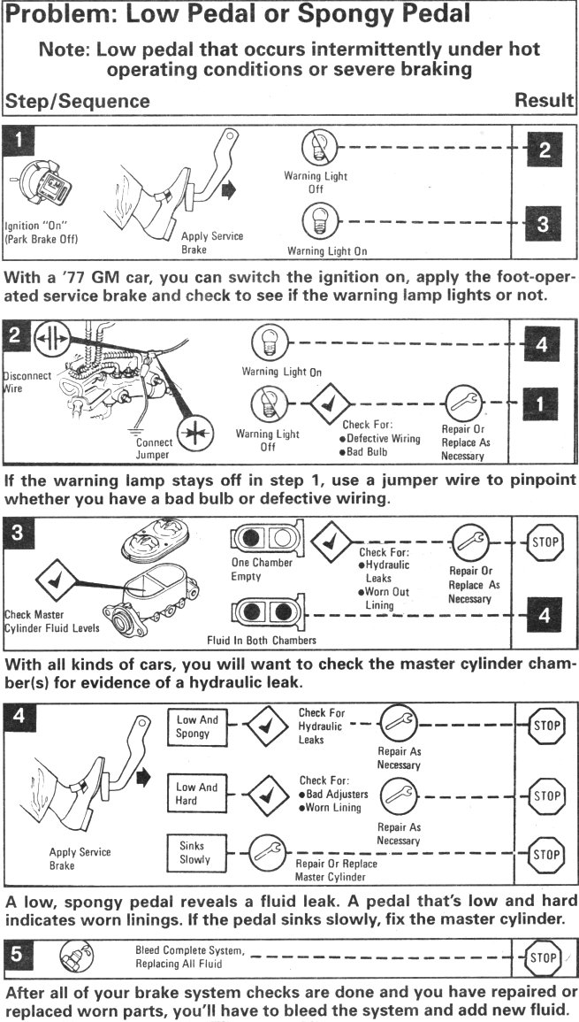
January 27, 2000By; John Gunnell If your collector car runs like new, you will want to insure that it also
stops like it did the day that it left the factory. One sign of brake-system
problems is a brake pedal that goes quiet low to the floorboard when pushed
down. A second sign of work being needed is a pedal with a "spongy"
feeling. Both of these conditions can exist in a car with manual brakes or one
with power brakes. The accompanying diagnosis-and-repair chart is based on a '77
General Motors car which had power disc brakes as standard equipment. In an
older car with manual brakes, the basic troubleshooting process would be
similar, but you would not have to start the car to activate the power-brake
booster. Also, if the car is new enough to have a brake-system warning light, you
will have to turn the ignition on, with the parking brake off, as illustrated in
step 1. Apply the service (foot) brake by pushing on the pedal. If the warning
light stays off, proceed to step 2. If the warning light goes on, go to step 3. If your later-model car has a brake warning light that went off in step
1, disconnect the warning light wire as shown in step 2. Then connect a jumper
wire as seen in the illustration. If the warning light now goes on, proceed to
step 4. If the warning light remains off, check for a bad bulb or defective
wiring. Replace the bulb or repair the wiring as necessary. Whatever year, make and model your collector car is and whether it has
manual or power brakes, a low or spongy pedal is probably going to require
checking and fixing the master cylinder, as illustrated in step 3. Older cars
will have a fluid chamber and newer ones will have two chambers, one large and
one small. The fluid level in the master cylinder should be up to factory
specifications as noted in your factory service manual or after market repair
manual. If one chamber is empty, check for hydraulic leaks or worn out linings.
If there's a leak, you can often fix it with an inexpensive repair kit. However,
professionals today prefer using a new master cylinder. Last summer I took my '53 Pontiac to a Firestone store for what I thought
would be a simple replacement of a section of brake line. By the time the job
was over, the car had all-new lining and new wheel cylinders. The rear linings
came from a local mechanic named Al Suehring, who picks up lots of old-car parts
at swap meets. I purchased the rear wheel cylinders at the Iola Old Car Show for
about $20.00 each. When the front wheel cylinders and linings also turned out to be bad, I
mail ordered all of the components from Kanter Auto Parts of Boonton, NJ. Fred
and Dan shipped them overnight and I go the car back in time for a rally in Lake
Geneva, WI. Getting back to later-model GM cars, if step 3 revealed fluid in both
chambers, it's time to go through all the checks in step 4. If the pedal is low
and spongy, check for and repair hydraulic leaks. If the pedal is low and hard,
check for bad adjusters or worn linings or pads. If the pedal sinks slowly
towards the floorboard, you'll have to repair the master cylinder with a rebuild
kit or replace it. After all of the fixing is done, the final step is completely bleeding
all air from the brake system and replacing any fluid that you lost with new
brake fluid of the proper type.
|